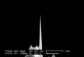
High Aspect Ratio (> 10:1) - Non-Contact / Tapping Mode - High Resonance Frequency - Reflex Coating
NANOSENSORS™ AR10-NCHR AFM tips are designed for non-contact or tapping mode AFM. This AFM probe type combines high operation stability with outstanding sensitivity and fast scanning ability.
For measurements on samples with sidewall angles approaching 90° NANOSENSORS™ produces specially tailored AFM tips. These AFM tips are FIB (Focused Ion Beam) milled to achieve a high aspect ratio portion better than 10:1 at the end of the common silicon AFM tip. This subtractive method of producing the high aspect ratio needle offers the advantage of high lateral stiffness and rigidity of the AFM tip.
The AFM probe offers unique features:
- length of the high aspect ratio portion of the AFM tip > 1.5 µm
- typical aspect ratio at 1.5 µm in the order of 12:1 (when viewed from side as well as along cantilever axis)
- half cone angle at 1.5 µm of the high aspect ratio portion typically < 2.8°
- guaranteed AFM tip radius of curvature < 15 nm
- highly doped silicon to dissipate static charge
- high mechanical Q-factor for high sensitivity
The reflective coating is an approximately 30 nm thick aluminum coating on the detector side of the AFM cantilever which enhances the reflectivity of the laser beam by a factor of about 2.5. Furthermore it prevents light from interfering within the AFM cantilever. As the coating is almost stress-free the bending of the AFM cantilever due to stress is less than 2% of the AFM cantilever length.
This AFM probe features alignment grooves on the back side of the holder chip. These grooves fit to the NANOSENSORS Alignment Chip.


 Due to their unique geometry the tips of the are more susceptible to tip damage by electrostatic discharge (ESD) than other Silicon-SPM-Probes.

